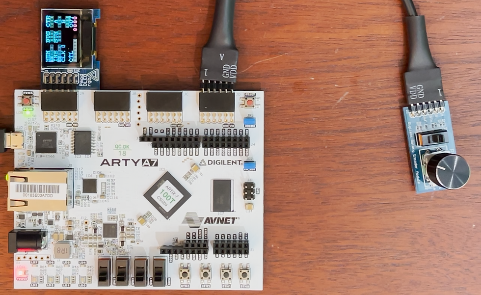
Continuing my project of building Ben Eater's 8-bit CPU on an FPGA, I created the clock module in VHDL. I connected that VHDL to a MicroBlaze soft-core processor so that I can display signals on an OLED display.

The clock module uses a rotary encoder, switch, and button. The rotary encoder allows changing the speed of the clock. The switch allows changing to manual clock pulsing, and the button allows toggling the clock signal (1/2 clock cycle per press). The clock output is displayed on an onboard LED. Additionally, the output of the clock signal is routed through a GPIO to the MicroBlaze, which then shows the status of different signals on the OLED display (with the clock being the only live data displayed so far).

As far as the project details, this is a continuation of the OLEDrgb Pmod Walkthrough post. In that post, I detailed how to get the OLED display running. From there, I added VHDL for the clock implementation. This included VHDL to read from the rotary encoder, debounce the rotary encoder shaft and button, and a clock module to generate the clock output based on the inputs.

I then updated the block diagram in Vivado. I added the VHDL as an RTL module and connected the clock output of that module to an AXI GPIO.

After creating the bitstream and exporting the hardware, I imported the hardware into a Vitis workspace. In Vitis, I read the signal from the GPIO and update the OLED display accordingly (snippets below).
See it in action below. (The zoomed in OLED display in the video is just a static image).
Next Steps
Ready to connect more VHDL signals from the 8-bit CPU to the OLED display. :)


Comentários