Most Arduino kits come with a basic joystick with an integrated push button. I had one these sitting around and decided to figure out how to interface it with my 6502 build, hoping to connect it to one of my VIAs.
The joystick has five connections: ground, power, x-axis, y-axis, and push button switch. As the joystick is an analog joystick, the x and y movement outputs a voltage on the associated pins that ranges from ~0V to ~5V. The 6502 and VIA are digital and work with 0V and 5V, having a middle ground that is neither high nor low. In the case of the W65C22S, low is anything from 0V to ~1.5V, and high is anything from 5V down to ~4V.
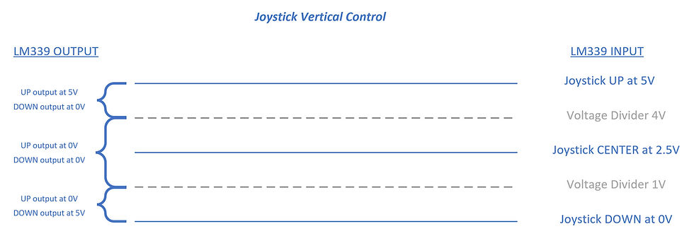
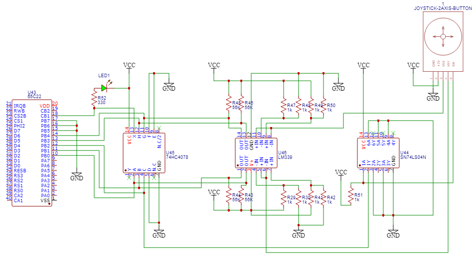
My first challenge was to convert the analog output of the joystick into a digital input for the VIA. To accomplish this, I used a set of simple voltage dividers and an LM339 comparator to split the analog joystick output into four signals -- left, right, up, and down. As the joystick is pushed in a direction, the associated signal will go high (see image below for an example of the vertical control analog to digital conversion). The joystick button press simply connects the switch (SW) signal to ground. At this point in the process, I had a momentary switch from the joystick and four digital outputs of the LM339. I pulled the joystick SW signal high with a pull-up resistor and ran the signal through a 74LS04 inverter. Now, I had five signals, each going high when their respective actions were taken: left, right, up, down, and press. I connected these five signals directly to PORTB of VIA2.


I still had the problem of letting the 6502 know when there was joystick interaction. I suppose I could have constantly polled the VIA port for the data, but I decided to use an interrupt. To get a single interrupt signal for the joystick, I ran all five joystick digital signals into a 74HC4078 8-input NOR gate. I connected the X output to CB1 on the VIA. Essentially, if any of the five joystick signals went high, the VIA CB1 interrupt would be pulled low (triggering the interrupt).
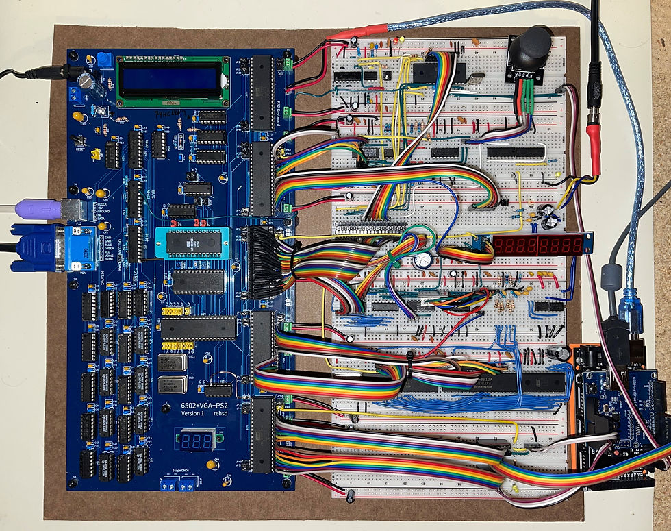
To finalize the hardware portion of the solution, I added an LED to the interrupt line from X to CB1. This would let me see when an interrupt was occurring (LED on = no interrupt; LED off = interrupt). The resulting schematic and breadboard circuit:


Now I needed to handle the interrupt in assembly code, read the joystick data, and do something with that data. As of this writing, the latest version of my ROM assembly is available here. Relevant portions:
;VIA2 Address Line A12
PORT2B = $5000
PORT2A = $5001
DDR2B  = $5002
DDR2A  = $5003
PCR2   = $500C
IFR2   = $500D
IER2   = $500E

;VIA Pins
JOYSTICK_DOWN           = %00000001
JOYSTICK_UP             = %00000010
JOYSTICK_PRESS          = %00000100
JOYSTICK_RIGHT          = %00001000
JOYSTICK_LEFT           = %00010000

lda #%10010000    ;Enable CB1 interrupt
sta IER2

lda #$00      ; Set all pins to input
sta DDR2B

irq:
  pha ;a to stack
  phx ;x to stack
  phy ;y to stack
  BIT  IFR2			; Check status register for VIA2
  BMI  VIA2_IRQ			; Branch if VIA2 is interrupt source

VIA2_IRQ:               ;joystick
  lda PORT2B
  sta $69
  AND #JOYSTICK_DOWN
  bne Handle_Joystick_Down
  lda $69
  AND #JOYSTICK_PRESS
  bne Handle_Joystick_Press
  lda $69
  AND #JOYSTICK_LEFT
  bne Handle_Joystick_Left
  lda $69
  AND #JOYSTICK_RIGHT
  bne Handle_Joystick_Right
  lda $69
  AND #JOYSTICK_UP
  bne Handle_Joystick_Up
  ;falls into VIA2_IRQ_OUT

VIA2_IRQ_OUT:
  lda #$D0  ;delay duration, counting from $D0 to $FF
  sta delayDurationHighByte
  jsr Delay

  ;read the port. if still bits there, repeat the interrupt handler -
                ;allows holding the joystick to keep cursor moving
  lda PORT2B
  cmp #$00
  bne VIA2_IRQ

  jmp irq_done

Handle_Joystick_Left:
  jsr RestoreCurrentPixelInfo
  ldx fill_region_start_x
  dex
  stx fill_region_start_x
  jsr StorePrevPixelInfo
  jsr DrawPixel
  jmp VIA2_IRQ_OUT
Handle_Joystick_Right:
  ...
Handle_Joystick_Press:
  ...
Handle_Joystick_Up:
  ...
Handle_Joystick_Down:
  ...
irq_done:
  ply ;stack to y
  plx ;stack to x
  pla ;stack to a
  rti
The Handle_xxx routines move a pixel around the screen and allow toggling of drawing as the pixel is moved. The result can be viewed in the following video.
I later implemented a USB mouse using very similar code, taking in the movement and button press signals directly from an Arduino (to which the mouse is connected).
For a future video, I could walk through the assembly code I have up to this point for drawing on the screen, using Ben's World’s worst video card. If that's of interest, let me know!
As will be the case with all of my posted mini-projects, I'm sure there is plenty of room for improvement. :)

Comments